
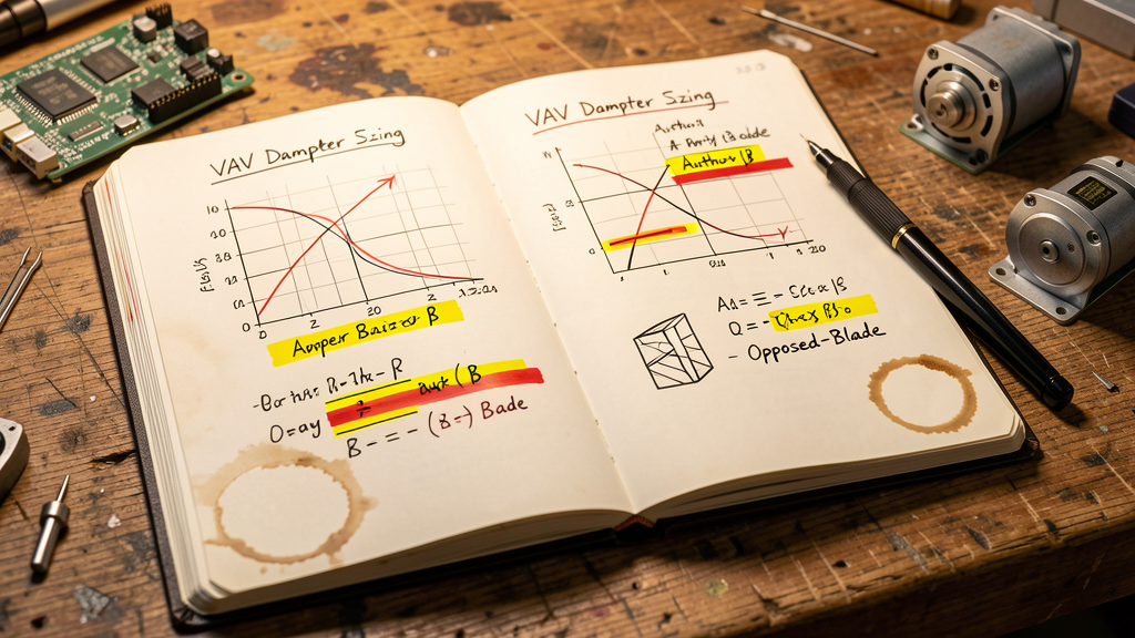
The VAV terminal unit damper is one of the most routinely mis-specified components in commercial HVAC design. A damper that is too large loses modulating authority at low flow; one that is too small generates excessive pressure drop and noise. Between ASHRAE Handbook applications data and manufacturers' catalogue curves, consulting engineers face a deceptively simple component that carries outsized consequences for comfort and energy performance.
The Two Damper Families: Opposed-Blade vs Parallel-Blade
All VAV terminal dampers fall into two fundamental categories, each with distinct flow characteristics that drive selection decisions:
| Characteristic | Opposed-Blade | Parallel-Blade |
|---|---|---|
| Flow characteristic | Linear to modified-linear — predictable across full stroke | Quick-opening — exponential at low angles, flat beyond 60° |
| Best application | VAV volume control, modulating duty | Two-position isolation, minimum pressure drop when open |
| Pressure drop at full open | Higher — blades remain in the airstream | Lower — blades rotate parallel to flow |
| Noise | Generally quieter in modulating service | Can generate turbulence noise at partial stroke |
| Cost | Slightly higher due to linkage complexity | Lower — simpler linkage geometry |
For VAV terminal unit applications, opposed-blade dampers are the default selection. ASHRAE Handbook — HVAC Applications (Chapter 48) recommends opposed-blade dampers for modulating airflow control because their near-linear characteristic simplifies control loop tuning. Parallel-blade dampers are reserved for isolation duty — fire/smoke dampers, maintenance isolation, and bypass applications where the damper operates fully open or fully closed.
An oversized opposed-blade damper operating below 15% stroke for most of the cooling season is not saving money — it is creating hunting, noise, and premature actuator wear. The most common VAV specification mistake is selecting the damper for peak design flow rather than the turndown range where it will actually operate.
Sizing Methods: Beyond the Rule of Thumb
Three methods dominate damper sizing practice, and each produces different results for the same terminal unit:
| Method | Approach | Suitable For | Pitfall |
|---|---|---|---|
| Face velocity | Size damper for 6-8 m/s (1,200-1,600 fpm) at peak flow | Quick sizing during schematic design | Ignores turndown; damper may be oversized at minimum flow |
| Authority (β ratio) | Damper pressure drop = 15-25% of total branch ΔP at full flow | Detailed design — best modulating control | Requires accurate duct pressure calculations |
| Catalogue selection | Manufacturer software sizes damper based on inlet conditions | Final specification — endorsed by ASHRAE | Vendor lock-in if not cross-checked with authority method |
The authority method — maintaining damper pressure drop at 15-25% of the total branch pressure drop at design flow — produces the most linear installed characteristic. When the damper pressure drop is less than 10% of the system total, the installed characteristic distorts towards quick-opening behaviour regardless of the inherent blade characteristic. ASHRAE Guideline 36-2021 reinforces this with specific trim-and-respond logic that assumes the damper has adequate authority to deliver stable modulation.
Common Specification Mistakes
Three recurring errors appear in VAV damper specifications across markets:
- Specifying the damper by duct dimensions alone. A 300 mm round damper in a 300 mm duct may be the correct physical fit but the wrong aerodynamic selection. The damper free area ratio — typically 75-85% for opposed-blade dampers — means the actual flow area is smaller than the duct cross-section. Always specify damper size based on free area, not nominal duct diameter.
- Ignoring the actuator torque requirement at the pressure differential, not the static rating. Actuator catalogues quote torque at zero differential pressure. At 750 Pa closing pressure, the required torque can be 2-3 times the catalogue rating. Specify actuators for the worst-case shut-off pressure differential in the system — typically at the AHU discharge with all downstream VAV boxes closed.
- Omitting the minimum controllable stroke. Every damper-actuator combination has a practical minimum stroke below which the flow is uncontrolled. For opposed-blade dampers with standard electric actuators, this is typically 10-15% of stroke — corresponding to roughly 5-8% of design flow. Below this point, blade edge leakage and hysteresis dominate. Specify the turndown requirement explicitly: "damper-actuator assembly shall provide stable modulation from 15% to 100% of design flow."
BACnet and Modbus Integration
The actuator is no longer just a motor — it is a networked device. Modern VAV damper actuators carry native BACnet MS/TP or Modbus RTU interfaces, transmitting position feedback, cycle count, and torque data directly to the BMS. This shifts the specification from "spring-return, 0-10 V" to a data-rich integration decision:
| Feature | Analogue (0-10 V) | BACnet MS/TP |
|---|---|---|
| Position feedback | 0-10 V proportional signal — no diagnostics | Absolute position (0-100%), fault codes, cycle count |
| Predictive maintenance | Reactive — wait for failure | Cycle count trending; torque rise alerts before stall |
| Wiring | 3 wires per actuator to DDC controller | Daisy-chain on MS/TP trunk — fewer home runs |
| Cost delta | Baseline | 15-25% premium offset by wiring savings at scale |
For projects with more than 50 VAV terminals, the BACnet MS/TP actuator premium is typically recovered through reduced controller I/O and wiring costs — the damper actuator becomes a node on the trunk, eliminating individual analogue I/O points at the VAV controller.
Cross-Border Relevance: Singapore, Hong Kong, and Dubai
For firms operating across Asia-Pacific and the Middle East, damper selection standards converge on a common core with regional variations:
| Jurisdiction | Standard | Key Requirement |
|---|---|---|
| Singapore | SS 553:2016 (Code for Air-Conditioning and Mechanical Ventilation) | VAV dampers must maintain minimum outdoor air under all operating conditions — drives sizing at turndown |
| Hong Kong | Buildings Department PNAP APP-151 (ventilation requirements) | Fire/smoke damper integration with VAV terminal — dual-function assemblies common in HK high-rise |
| Dubai | Dubai Green Building Regulations, ASHRAE 90.1-2019 reference | High ambient temperature requires actuator thermal derating; specify 85 °C rated actuators for ceiling plenum installation |
A damper specification written to ASHRAE Handbook methods with 15-25% authority is accepted in all three jurisdictions without modification — the physics of airflow does not change at the border. The regional variations are in the supporting requirements: fire/smoke integration, actuator temperature rating, and minimum outdoor air compliance at turndown.
Bottom Line
VAV damper selection rewards the engineer who looks past the catalogue face velocity table. The three decisions that separate a well-controlled VAV system from a chronic comfort complaint are: opposed-blade dampers for modulating service, sized for 15-25% authority at design flow (not just face velocity), with BACnet-enabled actuators that report position and torque to the BMS for predictive maintenance. The material cost difference between the right damper and the wrong damper is typically under AUD 80 per terminal unit — a fraction of the rebalancing and occupant complaint cost of getting it wrong.
Have a VAV damper selection question?
Search the HVAC controls knowledge base — opposed-blade vs parallel-blade characteristics, damper authority calculations, BACnet actuator integration, ASHRAE Guideline 36 trim-and-respond logic. Ask Havi, the AI chatbot, for answers backed by engineering standards.
Ask Havi
Knowledge Base Q&A
- How do I select the right damper actuator torque?
- What's the difference between parallel-blade and opposed-blade dampers?
- What is damper authority and how is it calculated?
- How do I select a VAV terminal unit for a zone?
- How do I select an actuator for airfoil vs. standard damper blades?
Sources
- ASHRAE Handbook — HVAC Applications (2023), Chapter 48: "Valves and Dampers."
- ASHRAE Guideline 36-2021: "High-Performance Sequences of Operation for HVAC Systems."
- SS 553:2016 — Singapore Standard Code of Practice for Air-Conditioning and Mechanical Ventilation in Buildings.
- Buildings Department Hong Kong, PNAP APP-151: "Ventilation Requirements."
- Dubai Municipality Green Building Regulations and Specifications (2020), referencing ASHRAE 90.1-2019.
- Belimo Holding AG. "Damper Actuator Selection Guide — Torque Rating vs Differential Pressure" (2024).
Related Articles
- Continuous IAQ Monitoring Is Now Table Stakes for Commercial Buildings
- Air Handling Unit Coil Selection: A Technical Guide for Optimal Performance
- Modern BMS Integration: From Traditional DDC to IoT-Enabled Building Controls
Published July 2026. This article is part of the XINCA HVAC controls engineering knowledge base. For consulting engineers, commissioning agents, and facility managers specifying VAV terminal units in commercial buildings. Search the knowledge base at help.xinca.com.
#VAV #DamperSelection #BACnet #HVAC #BuildingAutomation #ASHRAE