
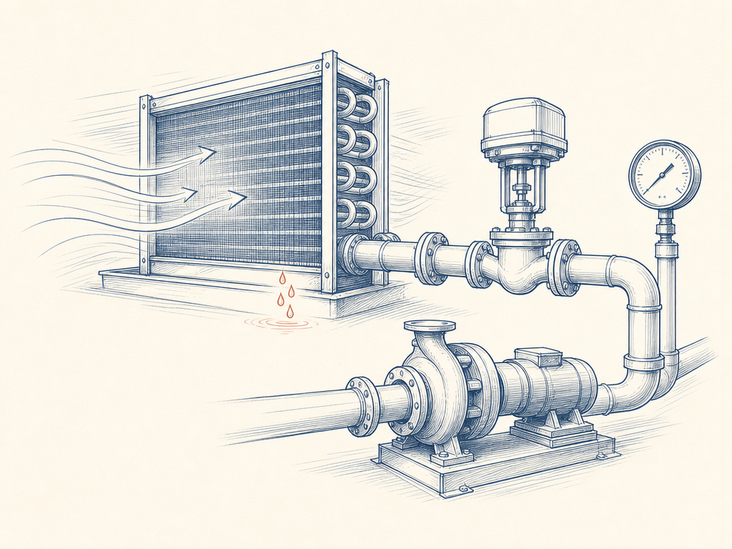
The pattern is familiar to anyone who has been handed the keys to a running building: the pumps are turning, the valves are modulating, the BMS shows no alarms — and the building still will not cool properly. In the four real cases below, all documented by the engineers who diagnosed them, the equipment turned out to be fine. What failed was balancing, setpoints, or installation. Each case yields a first check you can run before anyone orders replacement parts.
1. The valve that forgot how to modulate — Field Museum, Chicago
As the Field Museum consolidated more air handling units onto its central chilled water plant over twenty years, the system drifted out of balance. During a later investigation, engineers found the two-way modulating valves on the coils hydraulically closest to the distribution pumps behaving as on/off devices: they cracked open, the near-pump pressure immediately overflowed the coils, and the valves ran pinned at 100 percent, unable to hold discharge air temperature.
The worked number. A modulating valve only controls flow when it is the dominant resistance in its branch — that is valve authority, N = ΔP_valve ÷ (ΔP_valve + ΔP_circuit). Take a valve with 1.5 psi at full open in a branch whose circuit (excluding the valve) drops 13.5 psi: N = 1.5/15 = 0.10. At that authority, moving the valve from 50 to 100 percent open barely changes the flow — so the controller, seeing its setpoint unmet, drives the valve fully open. The valve looks broken. It is installed in a branch where no valve could modulate.
First check: when a valve hunts or pins at 100 percent, ask whether it is the branch closest to the pump. The fix in Chicago was rebalancing — which immediately restored modulation and flow to the remote coils — with pressure-independent control valves planned as the durable answer: a PICV holds its flow setpoint across the pressure swings that defeat a conventionally piped valve.
2. The valves installed backward — a 302-room hotel
A new hotel building with 350 fan-coil units and six air handling units could not be balanced: chilled water pumps ran near maximum while many distal rooms were starved of flow. The commissioning team's forensic step was to disassemble one of the automatic flow-limiting valves. Inside, two installation defects: a manufacturer batch with the flow-direction sticker printed the wrong way — valves installed backward — and rubber diaphragms that are position-sensitive; installed backward or missing, the valve opens with the flow and stops limiting at all.
The worked number. A flow limiter only limits once the pressure across it is inside its operating range — the project's TAB target was a minimum 2.0 ΔP at the worst-case unit's FLV. Below that floor, the "flow limiter" is just a fixed orifice: it neither limits nor protects, and the loop short-circuits through whichever valves fail open. That is exactly what the pumps were compensating for at nameplate amperage.
First check: before blaming the pump or the pipe sizing, pull one valve from the suspect batch and open it up — against the manufacturer's IOM, not the sticker. A batch defect is invisible from outside; it costs one valve teardown to find.
3. The setpoints nobody audited — a telecom facility in Illinois
A 350,000 sq ft telecom building called its design team back one year after a chiller plant upgrade. The symptom list: the chiller tripped on low flow several times a week; the plant saw a 3°F delta-T (low delta-T syndrome); space humidity sat at 62–65 percent; and pump VFDs put in bypass overheated and tripped. The audit found three wrong numbers doing all that damage:
- The chiller's flow-protection DP switch was set to full design flow, 189 gpm, when the manufacturer's specified minimum was 100 gpm — every flow condition between the two looked like a fault.
- The bypass flowmeter was uncalibrated and held its valve 100 percent open, pressurising the system and depressing the delta-T.
- Pumps were controlled to hold 18 psi across the most remote AHU coil's pressure-independent valve — against a design requirement of 5 psi — unnecessarily pressurising the loop and wasting pump energy.
The worked number. 18 psi where 5 psi is required is 3.6 times the differential the coil actually needs — pump head spent pressing water through valves for no heat-transfer benefit, with the bypass dumping it back to the chiller at 3°F. The verified fixes: DP switch reset to the manufacturer minimum (100 gpm), pumps reset to 5 psi at the remote coil, flowmeter calibrated and bypass held at 100 gpm. With those three changes the plant ran on one pump, and the VFD in bypass never rode low enough on its curve to trip.
First check: audit every protection and control setpoint against the manufacturer's minimum — not the design nominal. Design flow is a sizing number; the manufacturer's minimum flow is the number the chiller's protection actually needs.
4. The coil that rained — moisture carryover
The mechanism is simple hydraulics: air moving across a wet cooling coil shears condensate off the fin edges, and above a velocity threshold it carries droplets downstream — wet ducts, damp ceiling tiles, elevated supply humidity. The reference calculation: 10,000 CFM through a 20 ft² coil face equals 500 fpm. Standard coil-selection practice keeps cooling-coil face velocity below published carryover limits — under about 550 fpm, with 500 fpm a common specification ceiling.
The worked number. Face velocity = airflow ÷ coil face area. The formula runs in both directions: given the airflow you can check the coil you have; given a velocity ceiling you can size the coil face you need (10,000 CFM ÷ 500 fpm = 20 ft² of face area). A coil that carries over is telling you one of those two numbers is wrong.
First check: calculate face velocity from the fan's actual CFM and the coil's published face dimensions before condemning the drain pan or the trap.
The pattern
| Symptom | First check | Case |
|---|---|---|
| Valve pins at 100%, hunts like on/off | Valve authority / proximity to pump | Field Museum |
| Pumps at max, distal zones starved | Teardown of one flow limiter from the batch | Hotel TAB |
| Trips, high RH, hot VFD bypass motors | Setpoint audit vs manufacturer minimums | Telecom Cx |
| Wet ducts, pooling downstream | Face velocity from actual CFM ÷ face area | Coil carryover |
None of these failures were fixed by replacing the "broken" equipment. All four were found by measurement — a pressure reading, a teardown, a setpoint audit, a velocity calculation. That is the casebook's whole argument: in a hydronic system that has flow but will not cool, the first tool is arithmetic, not a purchase order.
Once the measurement has named the fault, the fix usually reduces to one or two components:
- Cases 1 and 3 — the valve that cannot modulate and the coil held at 3.6× its design differential: a pressure-independent valve holds its flow setpoint across the pressure swings that broke both systems. Specified by size and protocol, e.g. a DN15 pressure-independent control valve with BACnet/Modbus integration.
- Case 2 — verify actual flow, not stickers: the TAB lesson is that flow must be measured where it happens. Field hardware for that check: an insertion paddle flow switch (IP67) or a compact inline water flow switch rated to 10 bar.
XINCA lists these online at shop.xinca.com as an ecommerce partner of an authorised supplier — the catalogue carries the full range of air-side, water-side and fluid-control components referenced throughout this knowledge base.
#ChilledWater · #Hydronics · #PICV · #Commissioning · #HVAC · #BuildingServices
Have a chilled-water diagnosis question?
Search the HVAC controls knowledge base — valve authority, PICV selection, low delta-T, coil face velocity. Ask Havi for answers backed by engineering standards.
Ask Havi
Knowledge Base Q&A
- How do I size a control valve Cv for a chilled water coil?
- What is valve authority and why does it matter?
- What is the difference between pressure-independent and pressure-dependent valves?
- What flow sensor types are used in HVAC hydronic systems?
- How do I design a low-ΔT syndrome solution for chilled water plants?
- When should I use a 2-way vs 3-way control valve?
- How do I commission a VAV airflow sensor?
- What is the optimal placement for a chilled water differential pressure sensor?
- How do I troubleshoot a hunting control valve?
Sources
- Consulting Specifying Engineer. Case study: Pressure-independent control valves will update HVAC system (Field Museum, Chicago). csemag.com
- Consulting Specifying Engineer. Case study: Testing, adjusting and balancing solves issues in chilled water systems. csemag.com
- Consulting Specifying Engineer. Commissioning solves operational issues, saves energy (telecom facility, Illinois). csemag.com
- MEP Academy. Water Coils Explained. mepacademy.com
- ASHRAE-based coil selection guidance — Advanced Coil Selection (carryover-limited face velocity, <550 fpm). ashraemadison.org
- Campbell-Sevey. What Causes Condensate Carryover on Cooling Coils? (≤500 fpm practice rule). campbell-sevey.com
Related Articles
- Air Handling Unit Coil Selection Guide
- Control Valve & Hydronic Balancing Guide
- Modern BMS Integration: From Traditional DDC to IoT-Enabled Building Controls
Published September 2026. This article is part of the XINCA HVAC controls engineering knowledge base. For consulting engineers, commissioning agents, and facility engineers diagnosing chilled-water systems in commercial buildings. Search the knowledge base at help.xinca.com.
Get latest published articles from Havi pushed to you on Telegram.